Difference between revisions of "Campursoft ROM Board"
From CPCWiki - THE Amstrad CPC encyclopedia!
(→PCB) |
|||
| (13 intermediate revisions by 2 users not shown) | |||
| Line 1: | Line 1: | ||
The [[Campursoft]] ROM-Board is an 8 slot ROM board. | The [[Campursoft]] ROM-Board is an 8 slot ROM board. | ||
| + | It is made of 2 single sided PCB, one holding the ROM mapping and decoding, one holding the ROMS. | ||
| + | Two ROM-board can be used together to have make 16 ROM board. It was designed by Paul Collins. | ||
| + | == PCB == | ||
| + | <gallery> | ||
| + | File:CampursoftRomBox CTRL TOP.png|Control PCB Top | ||
| + | File:CampursoftRomBox CTRL PCB.png|Control PCB Bottom | ||
| + | File:CampursoftRomBox ROM TOP.png|ROM PCB Top | ||
| + | File:CampursoftRomBox ROM PCB.png|ROM PCB Bottom | ||
| + | </gallery> | ||
| − | + | == User Manual Scan == | |
| − | + | <gallery> | |
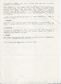
| − | + | File:Campursoft romboard Instructions page 1 of 3.png|Campursoft romboard instructions page 1 of 3 | |
| − | + | File:Campursoft romboard Instructions page 2 of 3.png|Campursoft romboard instructions page 2 of 3 | |
| − | + | File:Campursoft_romboard_Instructions_Page_3_of_3.png|Campursoft romboard instructions page 3 of 3 | |
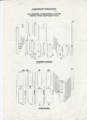
| − | + | File:Campursoft romboard schematics page 1 of 2.png|Campursoft romboard schematics page 1 of 2 | |
| + | File:Campursoft romboard Schematics page 2 of 2.png|Campursoft romboard schematics page 2 of 2 | ||
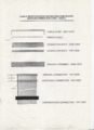
| + | File:Campurspft_romboard_silkscreen.png|Campursoft romboard silkscreen | ||
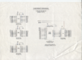
| + | File:Campursoft_romboard_connections.png|Campursoft romboard connections | ||
| + | </gallery> | ||
| + | |||
| + | ==Downloads== | ||
| + | * [[Media:CampursoftROMBOX.pdf|Campursoft Rombox user manual]] | ||
| + | |||
| + | ==Links== | ||
| + | * [http://www.paulslounge.co.uk/Computers/computers_index.htm Paul's website] | ||
| + | |||
| + | |||
| + | [[Category:Expansion ROM]] [[Category:Peripherals]] [[Category:manual]] | ||
Latest revision as of 12:01, 10 March 2018
The Campursoft ROM-Board is an 8 slot ROM board. It is made of 2 single sided PCB, one holding the ROM mapping and decoding, one holding the ROMS. Two ROM-board can be used together to have make 16 ROM board. It was designed by Paul Collins.
Contents
PCB
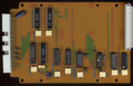
Control PCB Top
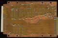
Control PCB Bottom
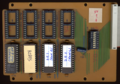
ROM PCB Top
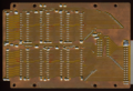
ROM PCB Bottom


User Manual Scan

Campursoft romboard instructions page 1 of 3

Campursoft romboard instructions page 2 of 3
Campursoft romboard instructions page 3 of 3

Campursoft romboard schematics page 1 of 2
Campursoft romboard schematics page 2 of 2
Campursoft romboard silkscreen
Campursoft romboard connections


