Difference between revisions of "Action Replay AMX"
From CPCWiki - THE Amstrad CPC encyclopedia!
(→Technical) |
(→Technical) |
||
| (6 intermediate revisions by 2 users not shown) | |||
| Line 13: | Line 13: | ||
== Technical == | == Technical == | ||
| − | * Has a write only I/O port | + | * The eagle schematics indicate INT is triggered, but the PCB drawings indicate [[NMI]] is connected. |
| + | * the static RAM is accessible between 0-1fff. It could be mirrored between 2000-3fff. | ||
| + | * Has a write only I/O port where A10=0 and A2=0. A8 of the port address (when '1'?) is used to 'activate' the ROMDIS signal (see IC1A) causing the CPC's ROM to be disabled. The static ram is then readable in the address space from 0-fff. A9 of the port address (when '1'?) (see IC1B) is used to 'activate' the RAMDIS signal causing the CPC's RAM to be disabled. This allows the static RAM to be read/written in the range 1000-1fff since access depends on A12 (see IC7A). It's not clear if both are visible. | ||
| + | It's not clear how the entire space can be written to. | ||
| + | |||
| + | * The unit has a switch for load/save, looks like A12 is driven depending on that. | ||
| + | |||
| + | All the above has been derived from schematics so may be wrong. This needs testing. | ||
== Pictures == | == Pictures == | ||
| Line 23: | Line 30: | ||
image:Datel_ActionReplayAMX_PCB_Top.jpg|PCB Top | image:Datel_ActionReplayAMX_PCB_Top.jpg|PCB Top | ||
image:Datel_ActionReplayAMX_PCB_Bottom.jpg|PCB Bottom | image:Datel_ActionReplayAMX_PCB_Bottom.jpg|PCB Bottom | ||
| + | image:Amstrad-CPC-Action-Replay-AMX-case.png|Unit front | ||
| + | image:Amstrad-CPC-Action-Replay-AMX-PCB.png|PCB Top | ||
</gallery> | </gallery> | ||
Latest revision as of 17:01, 23 February 2025
Action Replay A.M.X.
Made by Datel Electronics.
Now, thanks to Jose Leandro, the hardware specialist of the spectrum, with his famous page :
http://trastero.speccy.org/cosas/JL/JL.htm
We can know more about this hardware.
The hardware only has RAM and not ROM, therefore the device needs software programmed into the RAM to use it.
Contents
Technical
- The eagle schematics indicate INT is triggered, but the PCB drawings indicate NMI is connected.
- the static RAM is accessible between 0-1fff. It could be mirrored between 2000-3fff.
- Has a write only I/O port where A10=0 and A2=0. A8 of the port address (when '1'?) is used to 'activate' the ROMDIS signal (see IC1A) causing the CPC's ROM to be disabled. The static ram is then readable in the address space from 0-fff. A9 of the port address (when '1'?) (see IC1B) is used to 'activate' the RAMDIS signal causing the CPC's RAM to be disabled. This allows the static RAM to be read/written in the range 1000-1fff since access depends on A12 (see IC7A). It's not clear if both are visible.
It's not clear how the entire space can be written to.
- The unit has a switch for load/save, looks like A12 is driven depending on that.
All the above has been derived from schematics so may be wrong. This needs testing.
Pictures
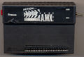
Unit front
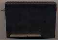
Unit back
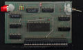
PCB Top
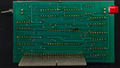
PCB Bottom
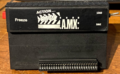
Unit front
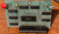
PCB Top


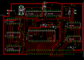
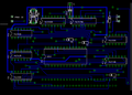
- Action Replay AMX Layout, thanks to Jose Leandro
Action Replay AMX - PCB Front
Action Replay AMX - PCB Back
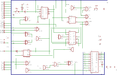
Action Replay AMX - Layout


Downloads
- Action Replay (Eagle).zip (Action Replay AMX files for Eagle)