Difference between revisions of "Connector:Monitor"
From CPCWiki - THE Amstrad CPC encyclopedia!
m |
|||
| Line 1: | Line 1: | ||
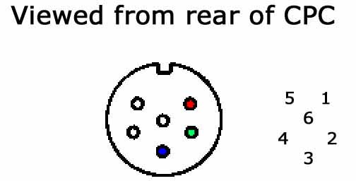
| − | Amstrad CPC Monitor port pinout | + | == Amstrad CPC Monitor port pinout == |
| − | [[Image: | + | [[Image:Cpc monitor pinout.jpg|image:cpc_monitor_pinout.jpg]] |
{| | {| | ||
| Line 36: | Line 36: | ||
This covers the CPC's RGB signal through the 6 pin DIN socket. | This covers the CPC's RGB signal through the 6 pin DIN socket. | ||
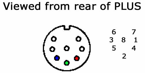
| − | + | == Amstrad PLUS Monitor port pinout == | |
| + | |||
| + | [[Image:Plus monitor pinout.jpg|image:plus_monitor_pinout.jpg]] | ||
| + | |||
| + | {| | ||
| + | |- | ||
| + | | ''Pin No.'' | ||
| + | | ''Signal Name'' | ||
| + | | ''Description'' | ||
| + | |- | ||
| + | | 1 | ||
| + | | Sync | ||
| + | | RGB switching control | ||
| + | |- | ||
| + | | 2 | ||
| + | | G | ||
| + | | Green analogue signal | ||
| + | |- | ||
| + | | 3 | ||
| + | | LUM | ||
| + | | Luminance | ||
| + | |- | ||
| + | | 4 | ||
| + | | R | ||
| + | | Red analogue signal | ||
| + | |- | ||
| + | | 5 | ||
| + | | B | ||
| + | | Blue analogue signal | ||
| + | |- | ||
| + | | 6 | ||
| + | | L | ||
| + | | Left audio signal | ||
| + | |- | ||
| + | | 7 | ||
| + | | R | ||
| + | | Right audio signal | ||
| + | |- | ||
| + | | 8 | ||
| + | | GND | ||
| + | | Common | ||
| + | |} | ||
| + | |||
| + | This covers the PLUS's RGB signal through the 8 pin DIN socket, that also includes stereo audio output. | ||
[[Category:Hardware]] | [[Category:Hardware]] | ||
Revision as of 06:22, 2 April 2009
Amstrad CPC Monitor port pinout
| Pin No. | Signal Name | Description |
| 1 | R | Red analogue signal |
| 2 | G | Green analogue signal |
| 3 | B | Blue analogue signal |
| 4 | Sync | RGB switching control |
| 5 | GND | Common |
| 6 | LUM | Luminance |
This covers the CPC's RGB signal through the 6 pin DIN socket.
Amstrad PLUS Monitor port pinout
| Pin No. | Signal Name | Description |
| 1 | Sync | RGB switching control |
| 2 | G | Green analogue signal |
| 3 | LUM | Luminance |
| 4 | R | Red analogue signal |
| 5 | B | Blue analogue signal |
| 6 | L | Left audio signal |
| 7 | R | Right audio signal |
| 8 | GND | Common |
This covers the PLUS's RGB signal through the 8 pin DIN socket, that also includes stereo audio output.

