Difference between revisions of "Connector:Monitor"
From CPCWiki - THE Amstrad CPC encyclopedia!
| Line 80: | Line 80: | ||
This covers the PLUS's RGB signal through the 8 pin DIN socket, that also includes stereo audio output. | This covers the PLUS's RGB signal through the 8 pin DIN socket, that also includes stereo audio output. | ||
| + | |||
| + | == KC Compact SCART Video Connector == | ||
| + | |||
| + | 1 Audio-Out R | ||
| + | 2 NC | ||
| + | 3 Audio-Out L | ||
| + | 4-5 GND | ||
| + | 6 NC | ||
| + | 7 RGB-Out Blue | ||
| + | 8 +12V (AV Mode) | ||
| + | 9 GND | ||
| + | 10 NC | ||
| + | 11 RGB-Out Green | ||
| + | 12 NC | ||
| + | 13-14 GND | ||
| + | 15 RGB-Out Red | ||
| + | 16 +1V (RGB Mode) | ||
| + | 17-18 GND | ||
| + | 19 Composite/FBAS-Out | ||
| + | 20 NC | ||
| + | 21 Shield | ||
| + | |||
[[Category:Hardware]][[Category:CPC Internal Components]] | [[Category:Hardware]][[Category:CPC Internal Components]] | ||
Revision as of 01:49, 29 January 2010
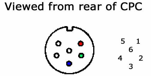
Amstrad CPC Monitor port pinout
| Pin No. | Signal Name | Description |
| 1 | R | Red analogue signal |
| 2 | G | Green analogue signal |
| 3 | B | Blue analogue signal |
| 4 | Sync | RGB switching control |
| 5 | GND | Common |
| 6 | LUM | Luminance |
This covers the CPC's RGB signal through the 6 pin DIN socket.
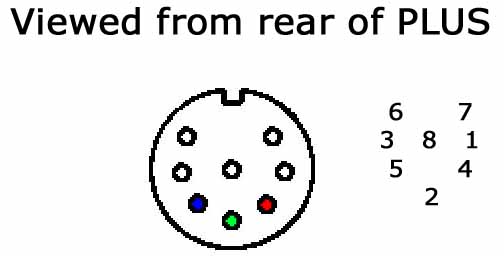
Amstrad PLUS Monitor port pinout
| Pin No. | Signal Name | Description |
| 1 | Sync | RGB switching control |
| 2 | G | Green analogue signal |
| 3 | LUM | Luminance |
| 4 | R | Red analogue signal |
| 5 | B | Blue analogue signal |
| 6 | L | Left audio signal |
| 7 | R | Right audio signal |
| 8 | GND | Common |
This covers the PLUS's RGB signal through the 8 pin DIN socket, that also includes stereo audio output.
KC Compact SCART Video Connector
 1     Audio-Out R
 2     NC
 3     Audio-Out L
 4-5   GND
 6     NC
 7     RGB-Out Blue
 8     +12V (AV Mode)
 9     GND
 10    NC
 11    RGB-Out Green
 12    NC
 13-14 GND
 15    RGB-Out Red
 16    +1V (RGB Mode)
 17-18 GND
 19    Composite/FBAS-Out
 20    NC
 21    Shield

